• About us
en
ites
  • Plant Design Software
    • ESAPRO Suite
      • Process Design
      • Plant Design
      • Electrical Design
      • Add-ons
    • Resold Products
  • Training and Support
  • Case histories
  • About us
  • News
    • All
    • News
    • Magazine
  • Contact
    • Contact us
    • Request Demo
    • Work with us
Request Demo
Magazine

Single Source of Truth for P&ID and 3D Piping: Reducing Rework and Data Silos

Posted on 18 Jun at 13:58
Francesco Pais
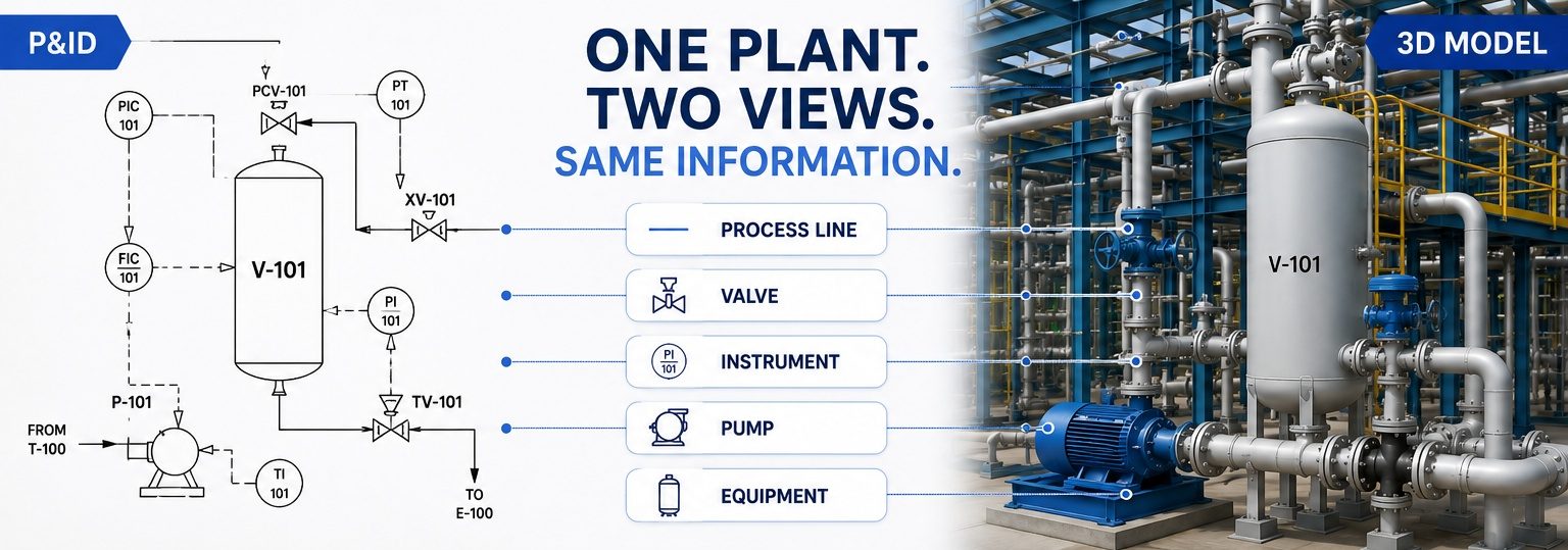
P&ID and 3D piping model representing the same industrial plant from complementary perspectives

In an industrial project, the P&ID and the 3D piping model describe the same plant from two different but complementary perspectives.

The P&ID defines process logic, lines, equipment, valves and instrumentation. The 3D piping model represents the physical arrangement of those elements, showing how piping systems are routed through the plant and how they interact with equipment, structures, supports and other disciplines.

Both are essential. The challenge begins when they stop evolving consistently.

A line may exist in the P&ID but not yet be reflected in the 3D model. A diameter may be updated by one discipline but not by another. A valve may be replaced without the change being propagated throughout the related project documentation.

These situations rarely originate from design mistakes. More often, they arise because project information is managed across multiple documents, systems or teams, making it difficult to maintain alignment over time.

This is why many engineering organizations are increasingly focusing on two closely related concepts: Single Source of Truth and Engineering Data Management.

The goal is not simply to manage more information, but to ensure that process, piping and other disciplines can rely on the same technical data throughout the project lifecycle.

Why P&ID and 3D Piping Models Tend to Drift Apart

P&ID and 3D piping models are maintained by different disciplines, each with its own responsibilities, priorities and workflows.

Process engineers focus on process requirements, operating conditions and functional plant information. Piping designers focus on routing, constructability, space constraints and 3D modeling activities.

In addition, engineering projects rarely follow a perfectly linear path. HAZOP studies, risk assessments, design reviews, client requests and regulatory requirements can introduce changes even when the 3D model has already reached 70–90% completion. When this happens, updates made to the P&ID must also be reflected in the 3D model, related documentation and project deliverables.

Another common source of misalignment originates much earlier in the project lifecycle: technical assumptions are often defined during bidding and proposal phases, where engineering teams must balance technical requirements, budgets and competitive deadlines. As projects progress, those assumptions frequently evolve, requiring process and piping teams to realign information that was initially created under different constraints.

As information is updated, reviewed and shared across multiple disciplines, the risk of inconsistencies naturally increases.

The Hidden Cost of Poor Engineering Data Management

Many organizations view misalignment between P&IDs and 3D models as a technical issue but in reality, it is often an engineering data management issue.

The actual cost is rarely the time required to modify a drawing or update a model. The larger cost comes from verifying information, checking documents, validating revisions and coordinating activities across disciplines: these activities can consume hundreds of engineering hours that add no direct value to the design itself.

As projects grow, teams often spend increasing amounts of time answering questions such as:

  • Which document contains the latest information?
  • Has this change already been implemented in the 3D model?
  • Is the line list still aligned with the latest P&ID revision?
  • Have all affected disciplines been informed?

Individually, these tasks may require only a few minutes. Across hundreds of changes, however, they can consume a significant amount of engineering effort and become a major source of rework.
Single Source of Truth for Process and Piping

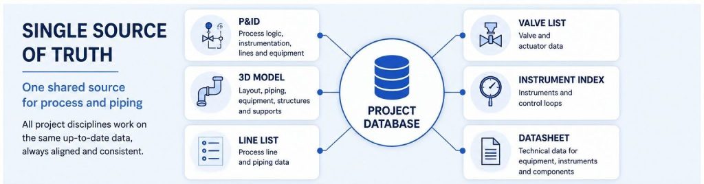
Single Source of Truth connecting P&ID diagrams, 3D piping models and engineering project documentation

In many projects, technical information is distributed across multiple documents.

Besides the P&ID and the 3D model, teams may manage line lists, valve lists, instrument indexes, datasheets, material take-offs, isometrics and spreadsheets used for project controls.

Problems arise when information is updated in one location but not in another. At that point, the team is forced to answer a simple but critical question: which information is correct?

This is precisely the challenge that a Single Source of Truth is designed to address. A Single Source of Truth provides a shared and trusted reference for project information, reducing duplication, inconsistencies and conflicting interpretations of the same data.

Within industrial plant design, this concept becomes particularly important when the P&ID, the 3D piping model and project documentation must evolve together throughout the project.

When the same information is maintained in multiple locations, the effort required to verify and reconcile changes increases significantly.

Not surprisingly, one of the most common causes of rework in engineering projects is the difficulty of managing changes consistently across different disciplines and deliverables.

Beyond technology itself, the objective of a Single Source of Truth is to ensure that all project stakeholders rely on the same information when making engineering decisions.

Signs That Your P&ID and 3D Model Are Out of Alignment

Misalignment between process and piping information is not always immediately visible. However, several recurring signs often indicate that project information is becoming fragmented.

  1. Frequent Cross-Checking Between Disciplines. Teams regularly compare documents to determine which information is current.
  2. Material Quantities Require Repeated Verification. Bills of materials and model-derived deliverables need constant manual validation.
  3. Isometric Drawings Require Additional Reviews. Isometrics generated from the 3D model require extra checks against the P&ID before release.
  4. Coordination Meetings Focus on Data Alignment. A significant portion of engineering meetings is spent clarifying which information should be considered valid.
  5. Different Teams Work With Slightly Different Information. This is often the most dangerous situation because inconsistencies may remain hidden until later project phases.

Integrated Piping Planning Requires More Than Layout

When discussing integrated piping planning, attention is often focused on routing, plant layout and 3D piping activities. These aspects are certainly important, but effective piping planning also depends on information consistency.

The 3D model is not merely a geometric representation of the plant. It is part of a larger information workflow that supports documentation, material management, construction deliverables and project coordination.

When process and piping information are not aligned, even routine tasks such as verifying a line size, updating a valve or confirming a piping specification can require additional reviews and manual checks.

This becomes even more important in spec-driven projects, where piping classes, specifications and components must remain consistent throughout the engineering lifecycle.

How to Improve Consistency Between P&IDs and 3D Models

There is no universal solution, but several principles can help reduce misalignment.

  1. Establish a Clear Source for Project Information. The more copies of the same information exist, the harder it becomes to keep them aligned.
  2. Strengthen the Connection Between Process and Piping. P&IDs and 3D models should not evolve as isolated engineering environments. Even when different disciplines work toward different objectives, the information must remain consistent. This is also one of the core principles of concurrent engineering, an approach in which multiple disciplines collaborate in parallel and share information throughout the development of the project.
  3. Verify Consistency Throughout the Project.Waiting until the final stages to identify inconsistencies often leads to avoidable rework.

From P&ID to 3D: The Value of an Integrated Database

Many companies rely on procedures, spreadsheets and manual checks to maintain consistency between process and piping information.

This approach may be sufficient for small projects. However, as projects grow, the amount of information that must be managed increases significantly.

In these situations, the value of an integrated platform is not simply having one tool for P&IDs and another for 3D piping design.

The real value lies in enabling multiple disciplines to work from the same project information.

With ESAPRO P&ID and ESAPRO 3D Piping, process and piping design are connected through a multidisciplinary engineering approach supported by a shared integrated database.

Information defined in the P&ID is no longer isolated within a drawing. Instead, it can be shared and reused throughout subsequent engineering activities. This approach helps reduce data duplication, minimize manual data re-entry and improve consistency across disciplines, helping engineering teams spend less time checking information and more time designing.

By working from a shared technical database, engineering teams can improve traceability, reduce inconsistencies and better support a true Single Source of Truth throughout the project lifecycle.

The result is not only greater efficiency, but also improved control over engineering information.

Are you struggling to keep your P&IDs and 3D piping models aligned?

One of our experts will show you how to improve coordination between disciplines and reduce information inconsistencies throughout your projects.

REQUEST A DEMO

Similar posts

Best P&ID software with structured project data, native DWG, automatic lists, spec-driven design and revision control

Best P&ID Software: Key Criteria for Choosing the Right One

PIMM Plant Information Modeling & Management as a connection between BIM and the industrial Digital Twin

PIMM: Plant Information Modeling & Management for Industrial Plants

P&ID change management process to control revisions and reduce rework

P&ID Change Management: How to Control Changes and Reduce Rework

The ESAPRO suite

Software for industrial plant design. 800+ clients and 4,000+ installations worldwide.

Discover the ESAPRO suite

Latest articles

See you at Ecomondo 2026

4 weeks ago

ESAPRO moves to the cloud: simpler, more flexible licensing

4 weeks ago

Summer office closure

2 months ago

Categories

News 17
Magazine 47
Logo-Esain-Anniversary-white

About us

Since 1994, ESAIN has developed integrated software for industrial plant design. The ESAPRO suite covers P&ID, 3D piping modelling and electrical design, with over 800 clients and 4,000 installations worldwide.

The Company has benefited from the resources of the PR FESR LIGURIA 2021-2027, Bando Digitalizzazione 1.2.3

Coesione_Italia_Liguria

Products

  • ESAPRO P&ID Software
  • ESAPRO 3D Piping Software
  • ESAPRO Cable Trays Software
  • Add-ons
  • Resold products

Services

  • Training and support

News

See you at Ecomondo 2026

4 weeks ago

ESAPRO moves to the cloud: simpler, more flexible licensing

4 weeks ago

Summer office closure

2 months ago

Case history

  • All case histories

Follow us

LinkedIn
YouTube

ESAIN s.r.l. · +39 010311544 · info@esain.it · Via de Marini 1, WTC 8th floor – 16149 Genoa, Italy

Share capital € 50,000 · REA GE-347489 · P. IVA 03470480108

  • Privacy
  • Cookie