What Makes One P&ID Software Better Than Another?
Identifying the best P&ID software is not simply a matter of comparing a list of product names. More importantly, it means defining the criteria used to evaluate each solution. The most accurate answer is that the best tool depends on the projects an engineering department actually manages, the scale of the plants involved and how the process diagram needs to feed into the rest of the workflow, from piping design to project deliverables. However, one principle remains constant: a P&ID is only as valuable as the data it contains.
If the diagram is just a drawing, every list, check and revision becomes a manual task again. This guide outlines the practical criteria for evaluating P&ID software: diagram intelligence, a single source of data, automation of lists and deliverables, supported standards, compatibility with the rest of the workflow and the scale of the solution
As a practical example, we will refer to ESAPRO P&ID, the process design software within the ESAPRO suite, which ESAIN has been developing since 1994 and which has more than 4,000 installations worldwide.
Intelligent P&ID or Static Drawing: The First Key Difference
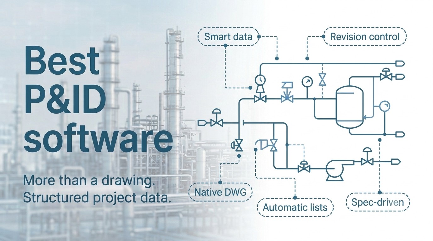
The first criterion distinguishes dedicated P&ID software from generic CAD systems adapted for creating process diagrams. In an intelligent P&ID, every symbol is an object with associated data: lines, valves, equipment and instruments contain attributes, specifications and connections, rather than simply graphical shapes. This structure is what turns the diagram into a reliable source of information for the entire project. Spec-driven design adds another level of control: inserted components are checked against the project piping specifications, so inconsistencies are identified while the diagram is being created, when they are still easy and inexpensive to correct. With a static drawing, the same error may remain unnoticed until manual checks are performed or, worse, until construction begins. The difference also becomes clear further downstream. An intelligent diagram passes structured information on to the rest of the project, whereas a static drawing provides only geometry that needs to be interpreted again. When evaluating a solution, it is therefore worth asking three questions: do the objects in the diagram contain data? Do piping specifications guide component selection? And what happens when a component does not comply with the relevant specification? The answers already reveal a great deal about the nature of the software.
A Single Source of Data, with Lists and Deliverables Generated from the Project
The second criterion is data consistency. In plant design projects, the same information appears in diagrams, lists and documents. If each document exists independently, every change has to be manually replicated across all of them. A properly structured P&ID solution stores all information in a single project database: data is entered only once and remains consistent throughout the project. The practical result is automation. From an intelligent diagram, line, valve, equipment and instrument lists can be generated automatically, exported to Excel and kept aligned whenever the diagram is revised. ESAPRO P&ID follows this approach and extends it through other add-ons within the suite. ESAPRO Instrumentation synchronises instrument specifications with process diagrams, ESAPRO Material Take Off generates piping bills of materials including flanges, fittings and reducers, while ESAPRO PDM Connector links diagrams to document management systems with automated revision management. When evaluating a P&ID solution, this is an important metric to consider: how many lists and project deliverables can be generated without manual counting or data entry?
Standards, Revisions and Compatibility: A P&ID Does Not Exist in Isolation
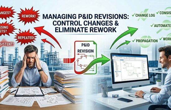
A process diagram is exchanged between designers, clients, suppliers and regulatory bodies. Another important criterion is therefore how well the software supports the standards and file formats used by everyone involved in the project. In terms of symbols and naming conventions, compliance with recognised standards is essential: ESAPRO P&ID is compliant with ISA and KKS standards. File format is equally important. DWG drawings made entirely of native entities remain readable by any compatible CAD system, without proprietary objects that require dedicated converters or viewers. This also helps protect the long-term accessibility of historical project archives. It is also important to assess the features that maintain consistency throughout the project lifecycle: automatic comparison between revisions of the same diagram, consistency checks between the P&ID and the plant’s 3D model, BIM integration and support for laser-scanner point clouds when working within existing plants, as is typically the case in revamping projects. These capabilities determine how well a P&ID solution performs in real-world projects: projects that change, undergo multiple revisions and must remain consistent from the first issue through to final delivery.
The Right Scale: Small and Medium-Sized Plants Have Their Own Requirements
Many plant design software rankings are based on the requirements of very large projects, and the systems developed for those organisations are designed around the needs of projects of that scale. For engineering companies or contractors designing small and medium-sized plants, the selection criteria are different: short installation and implementation times, a tool that designers can learn quickly, an investment proportionate to the size of the projects and an accessible supplier that can work directly alongside the engineering team. ESAPRO was developed for this type of project. It is a complete suite whose products communicate through the same database, it is quick to install and straightforward to use, and ESAIN supports customers through training and direct technical support, from initial implementation to day-to-day operation. Today, around 800 customers worldwide use the ESAPRO suite. For projects of this scale, fast implementation and the ability to communicate directly with the company developing the software are particularly valuable. When choosing the best P&ID software, the right question is therefore not which tool offers the greatest number of features, but which one is properly sized for the projects your engineering team actually needs to deliver.
How to Verify These Criteria Before Making a Decision
The criteria outlined in this guide have one important advantage: they can be tested directly on your own projects. Simply bring a real project to the software demo, including your diagrams and specifications, and see how the system manages data, lists and revisions. Three steps are particularly useful to observe: how the piping specification is configured, what the diagram can generate without manual intervention, and how a change is carried forward into the next revision. If the software can generate accurate lists, highlight inconsistencies and keep up with revisions during these tests, then the criteria described in this guide have been confirmed in a real project environment.