The dimensions and wall thickness of pipes are among the most critical factors to consider when designing an industrial plant. Pipe schedule calculation, the parameters that determine the pipe wall thickness, is essential to ensure that the pipeline wall can withstand the operating pressure and temperature of the fluid flowing through it.
This parameter can therefore be considered one of the key elements to ensure the safety of the entire piping system and to prevent leaks or ruptures that could damage the industrial facility and pose risks to personnel. For this reason, pipe schedule values are generally integrated into the , which include specific tools to simplify the creation of material lists with corresponding standard references (ASME, UNI, etc.).
Professionals involved in the design of an industrial plant must analyze in detail the idea provided by the client and carefully choose the materials best suited to withstand the pressure and temperature conditions that characterize this type of plant. Choosing the right materials is essential for the success of the project, ensuring the safety and reliability of each component.
Let’s explore the technical meaning of pipe schedule and the standard schedule numbers used to define pipe wall thickness.
What is pipe schedule and how to calculate it
This parameter refers to a standard classification system used to define pipe dimensions the wall thicknesses needed to withstand the pressure of the fluid. The pipe must be strong enough to meet the functional requirements defined during the design phase for the intended industrial plant.
The parameters of each piping line section are calculated using a combination of values for the pipe size and its wall thickness, with the goal of obtaining the most suitable schedule number. The pipe schedule (abbreviated SCH) is calculated to get a uniform relationship equal to 1000 times the expression p/S (SCH=1000*p/S) where “p” indicates the internal pressure and “S” the maximum allowable tension from the chosen material.
The pipe schedule calculation uses Barlow’s formula, which is equal to: t=pD/2S + c, where “t” indicates the thickness, “c” the corrosion allowance, and “D” the inside diameter. Combining the data will then give p=2(t-c)S/D, from which the schedule number of pipe as a function of the pipe wall can be obtained: SCH=2000*(t-c)/D.
Software for calculating pipe schedule
Modern 3D piping software includes features that can generate the various material lists needed for constructing an industrial plant. These tools also offer functions to define detailed line specifications, which may vary depending on the process conditions (fluid, temperature, pressure), and help determine the materials to use for different pipelines or line classes.
Among the most effective 3D piping modeling applications are ESAin’s 3D piping software, which also allow the definition of a “branch table”, a table of intersections where, for each diameter type, the corresponding branch components (e.g., couplings and tees) are listed for making necessary connections. Additionally, ESAin software enables fast definition of technical parameters essential for pipe construction, such as maximum commercial pipe length and the specific welding procedures required.
ESAin’s software provides dedicated functionality for defining a “thickness table”, which includes wall thickness values and pipe schedules for selected components. An archive of thickness classes is also available for assigning wall thickness and names to each nominal diameter.
Standards and tables for pipe size and thickness
The ASME (American Society of Mechanical Engineers) and ANSI (American National Standards Institute) are the main organizations that establish standard guidelines to be followed for the design, construction and maintenance of industrial plants. They also provide information on the internal pressure that can be withstood by piping: the Italian UNI standard, on the other hand, refers to nominal pressure.
Pipe wall thickness is defined according to the applicable ASME standard. While values may be given in millimeters or inches, ASME standard parameters are generally used as reference during material procurement. There are also specific standards for the piping of certain types of industrial plants: oil plants are an example, where the common standards are ASME B36.10 (welded and seamless steel) and ASME B36.19 (stainless steel).
Certified nominal pressures and pipe schedule equivalence tables
The pipe schedule is represented by a letter indicating the wall thickness: “STD” indicates a standard thickness, “XS” a larger one (extra-strong) and “XXS” a higher one (double extra-strong) while the associated numbers (5,10,20,30,40 etc.) represent increasing specific thickness values.
According to ASME standards, various types of certified nominal pressures exist. These may vary depending on the material, operating temperature, and other specific characteristics of the industrial system:
- 5S – Thin wall, typically used for low-pressure applications.
- 10S – Generally low certified pressures, depending on the material.
- 40S – One of the most widely used schedules, with higher certified pressures.
- 80S – Designed for high-pressure, high-temperature applications.
- 160S – Heavy-duty schedule for very high-pressure conditions.
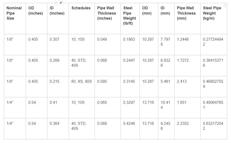
A useful pipe schedule chart equivalence table correlating schedule numbers, nominal dimensions, and wall thicknesses is provided in the following downloadable resource: