During the design of an industrial plant, a flow diagram is used to graphically represent processes and define the components within the plant. Designers create a process diagram, the P&ID (Piping and Instrumentation Diagram), which includes all the information related to piping, valves, in-line components, equipment, and instruments to be used.
With this technical drawing, designers will have at their disposal a graphical representation of the industrial plant, with which they can view in detail the various interconnections between equipment and the specifications of materials, which are essential for the construction and maintenance of the plant. It serves as the foundation for further studies of the piping layout and aims to represent the industrial project in its entirety: the various disciplines involved will be able to study the behavior of each component present within it.
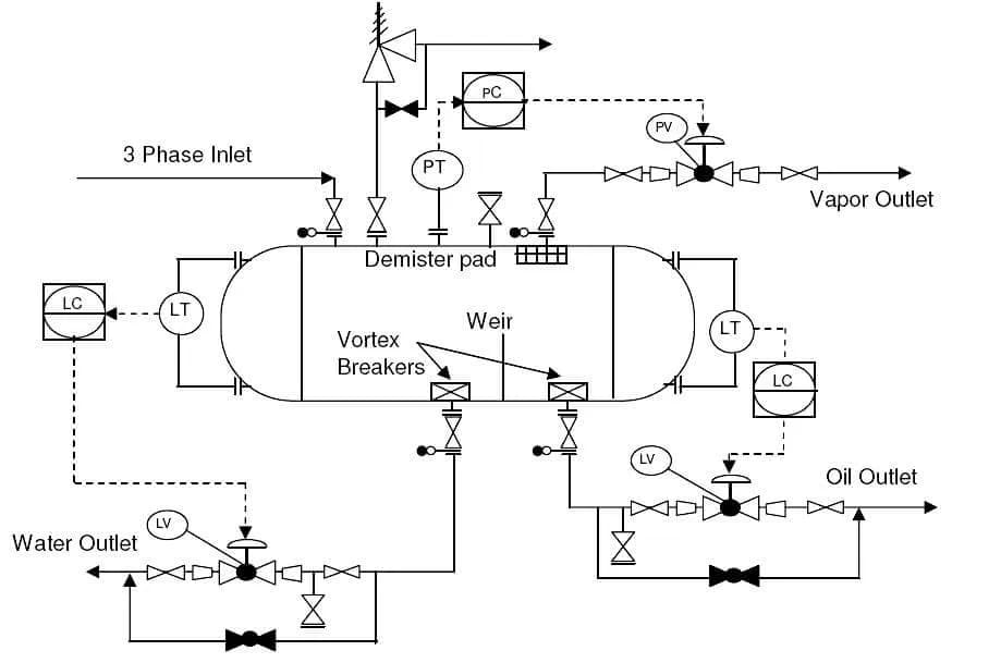
To facilitate the work of designers and engineers, the elements within the flow diagram are identified using a standard graphical representation that allows users to read the P&ID and describe the entire process: the P&ID symbols are connected by lines representing the plant’s piping.
What are the symbols used in P&ID?
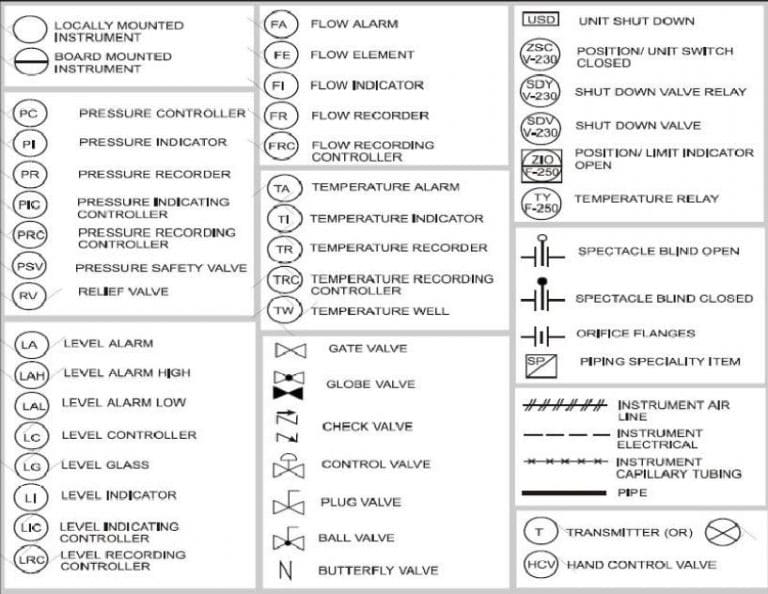
Flow diagrams use standard P&ID symbols defined by respective regulations (ISO, UNI, DIN, ISA, and KKS), which identify piping, control systems, equipment, and all other components. Each element is represented by a P&ID symbol and an alphanumeric code, which allows defining the process variable and the function of the component within the plant.
The graphic representation used to indicate plant components depends on the type of element analyzed.
These include:
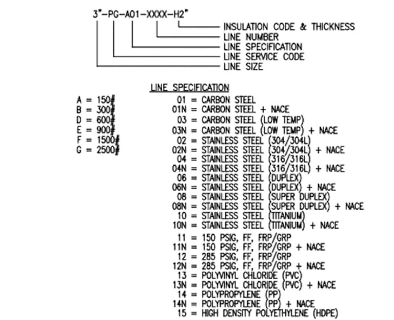
• P&ID piping symbols. Piping that connects the various components of an industrial plant is represented with specific symbols and may include additional properties such as size, pressure values, and material specifications. Creating a P&ID is often simplified by using “Piping Classes”, lists of allowed components for lines with specific characteristics. This feature, available in the best P&ID software like ESApro P&ID by ESAin, simplifies line
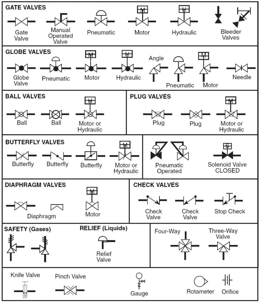
- P&ID valve symbols. Once the line is drawn, it can be completed by adding valves and components. Examples include control valves to prevent fluid backflow, globe valves, gate valves, ball valves, and butterfly valves, each represented with a specific symbol in the Piping and Instrumentation Diagram.
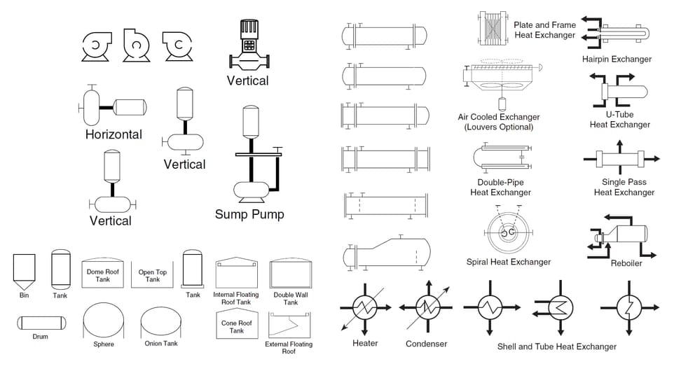
- P&ID equipment symbols. Examples include those used to represent various types of pumps (centrifugal, vacuum, screw, submersible, etc.), tanks, compressors (axial, reciprocating, rotary, etc.), mixers, and heat exchangers. Additional symbols define boilers, furnaces, oil burners, mixing reactors, and other existing equipment.
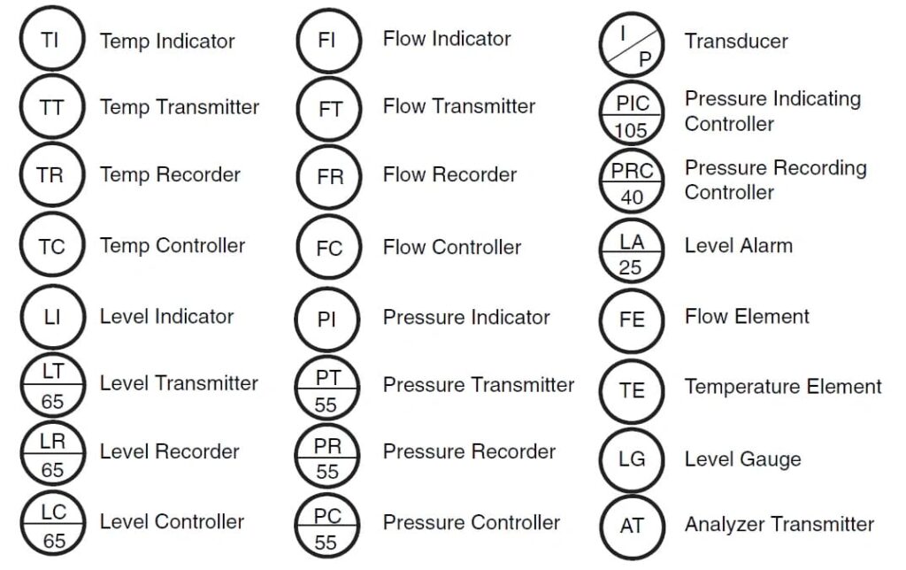
- Instrumentation P&ID symbols. Also contained in the flow diagram are graphical representations by which the instruments included within the plant are identified, providing information about interconnections with other components.
P&ID symbols library
Modern software for drafting process diagrams automatically provides lists of lines, valves, and instruments necessary for industrial plant design. These also include graphic libraries containing the symbols specified by standards, essential for accurately representing each component. Software used to create process diagrams also allows the addition of new graphic symbols: typically, the graphical part must be drawn in AutoCAD and then inserted into the software by selecting the appropriate category.
During the creation of the Piping and Instrumentation Diagram, it is also possible to use P&ID symbols library by modifying the existing symbology to adapt it to the project’s requirements. The information contained within it will be used to identify plant components: for example, during the generation of “Pipe Classes” and within material take-off lists.
Each graphical representation is generally identified within the software’s library with a code, allowing it to be uniquely identified in the P&ID symbol library: from piping to valves, from flow control components to generators, pumps, exchangers, and the symbols used to identify instrumentation, machinery, and general equipment.