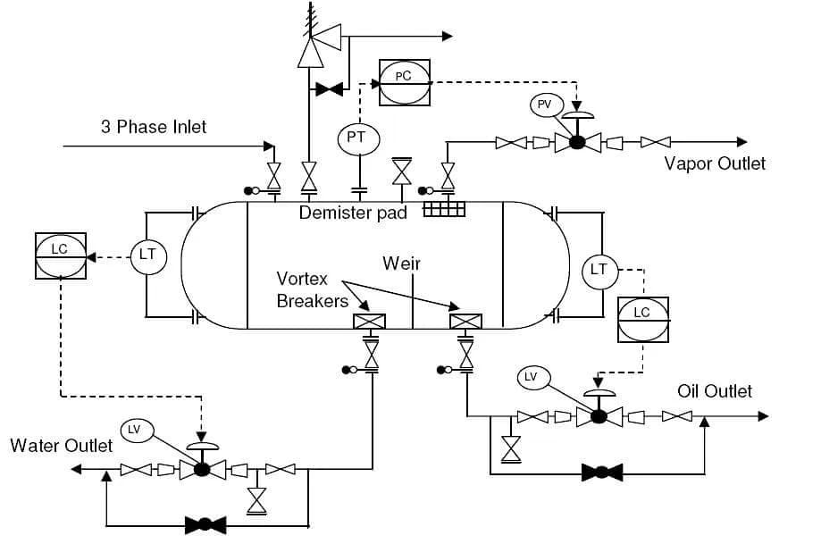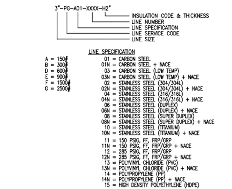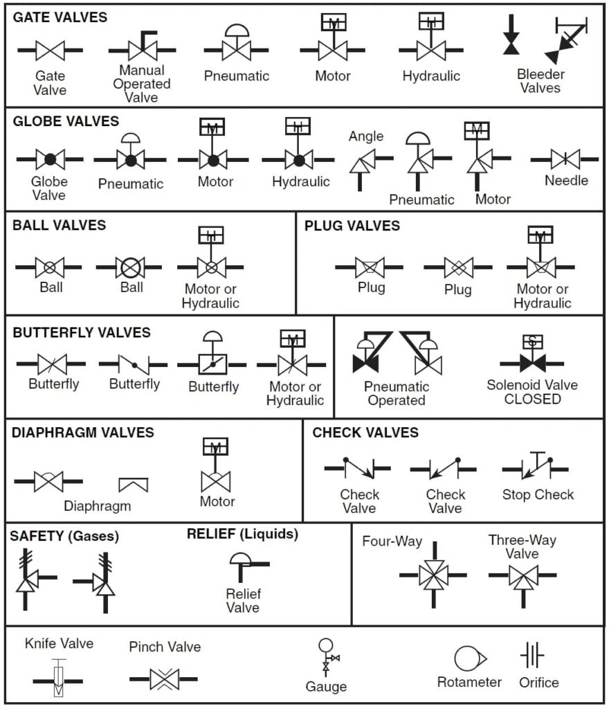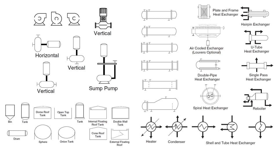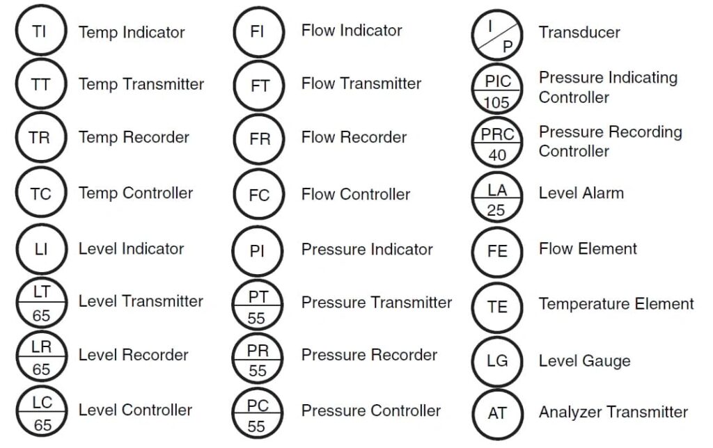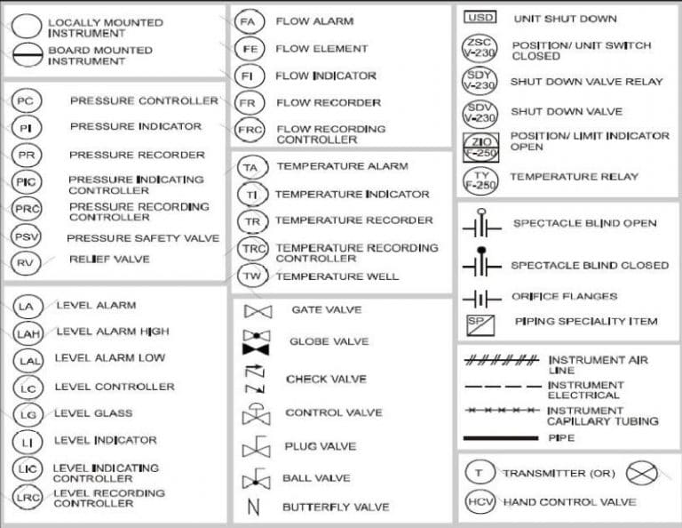
During the design of an industrial plant, a flow diagram is used to graphically represent processes and define the components within the plant. Designers create a process diagram, the P&ID (Piping and Instrumentation Diagram), which includes all the information related to piping, valves, in-line components, equipment, and instruments to be used.
With this technical drawing, designers will have at their disposal a graphical representation of the industrial plant, with which they can view in detail the various interconnections between equipment and the specifications of materials, which are essential for the construction and maintenance of the plant. It serves as the foundation for further studies of the piping layout and aims to represent the industrial project in its entirety: the various disciplines involved will be able to study the behavior of each component present within it.