


Industrial electrical wiring diagrams are essential tools in the design and maintenance of modern industrial plants. In this guide, you’ll learn what an industrial electrical diagram is, how to design one, and which software tools can help streamline the process. Understanding how to draw industrial wiring diagrams is key to ensuring efficiency, safety, and productivity in industrial automation systems.
What industrial electrical wiring diagrams are and how to draw them
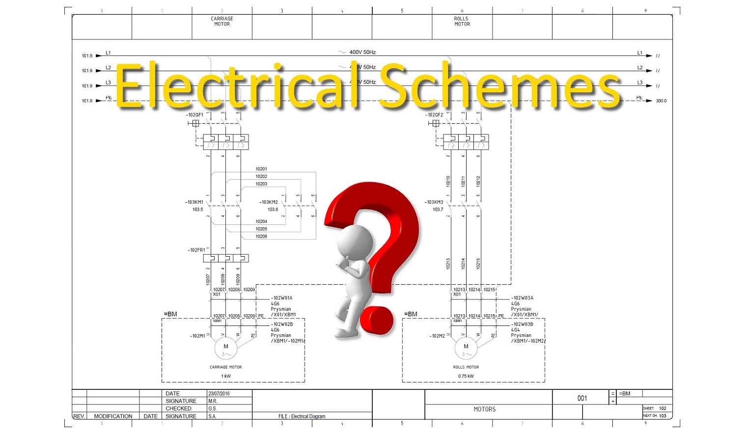
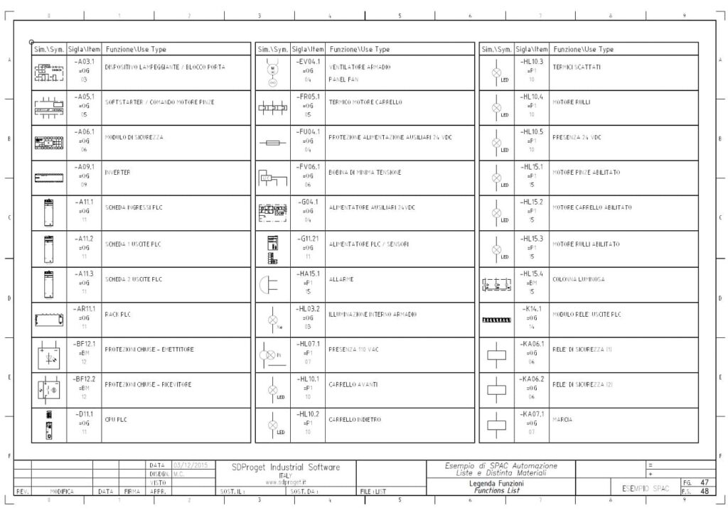
An electrical wiring diagram for industrial is a detailed schematic that shows the electrical connections, signals, and power flows between devices in an automation system. Each electrical component—whether a motor, switch, or sensor—is represented using standardized electrical symbols that clearly communicate its function and location. Lines connecting these symbols represent the flow of current and define how devices interact within the electrical system.
These diagrams are crucial during initial plant design, but also during troubleshooting, maintenance, and plant upgrades. They ensure that technicians and engineers can accurately interpret system configurations, identify failures, and make changes while maintaining full compliance with safety and engineering standards.
Electrical wiring diagrams for industrial plant design
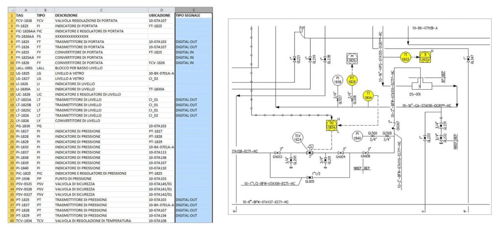
In modern industrial engineering, wiring diagram creation is tightly integrated with other plant design phases. After creating a , instrumentation and electrical teams use this data to generate an I/O list and detailed automation schematics.
Sharing real-time information between mechanical, instrumentation, and electrical engineering teams ensures proper alignment. For instance, motor power ratings or sensor specifications can be shared early, enabling precise and efficient electrical layout development. This integrated design workflow reduces errors and improves coordination throughout the plant lifecycle.
Best software to draw industrial electrical diagrams
Dedicated electrical CAD software has replaced manual drafting, accelerating productivity and improving accuracy in electrical wiring diagram design. Modern tools offer features like cross-referencing for relays and PLC I/O terminals, automated error checking, and BOM (bill of materials) generation.
Popular solutions such as SPAC Automazione support real-time validation and automation for industrial electrical wiring diagrams. Cable routing tools like ESApro Cable Routing optimize wiring paths, calculate copper demand, and validate tray fill rates—significantly reducing installation errors and design time.
Advanced integration allows export of industrial electrical wiring diagram to external electrical CAD platforms once cable lengths and routes are finalized. This seamless workflow ensures efficient collaboration and complete design documentation across engineering departments.
Request more information about industrial electrical wiring diagram
Are you looking to streamline your electrical engineering workflow or adopt modern CAD tools for industrial electrical wiring diagrams? Our experts can help you choose the best solutions to optimize your plant design process.
Similar posts


The ESAPRO suite
Software for industrial plant design. 800+ clients and 4,000+ installations worldwide.
Latest articles


Categories